In a successfully designed project, building systems, materials, and products must be integrated to create a unified whole that achieves the desired functional purpose. An integrated solution results from a design approach that considers the characteristics of each component proposed in the project and searches for opportunities for dual functions or for sharing of volume. This system integration approach represents a paradigm shift in building design and construction fields.
1. Integrated flooring systems in multistory commercial buildings
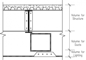 Most multi-story commercial buildings are very wasteful of the space above the finished ceiling and below the floor of the level above. This is the “sandwich” volume for various building systems such as: structures, HVAC, electrical, communications, plumbing, and fire protection. To make the design process simpler, the design team often allocates an independent volume to each of the systems, a typical example of which is shown in Figure 2. Under the floor, the structural spanning system has been given its own volume, having a horizontal extent equal to the footprint of the building and a vertical dimension great enough to accommodate the deepest spanning beam or truss. Beneath that volume, the HVAC system has been given its own volume, having a horizontal extent equal to the footprint of the building and a vertical dimension great enough to accommodate the largest duct in the system. Beneath that, electric lighting has been given its own volume, having a horizontal extent equal to the footprint of the building and a vertical dimension great enough to allow electric lighting fixtures to be maneuvered and inserted between the T-bars of the hung ceiling. The design process thereby becomes more like volume allocation, rather than system integration. In this process, vast amounts of the ‘sandwich’ volume are filled only with air.
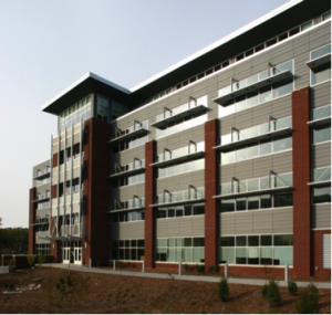 The North Carolina Wildlife Conservation Commission Headquarters and Exhibition Building was the first project in which an integrated flooring system had been applied to address the above issues. An effective approach to system integration is outlined in the following points: Beams running parallel to the light-admitting wall have a greater obstructive influence in blocking light entering through the wall than do beams running perpendicular to the light-admitting wall. Therefore, it is particularly desirable that the beams running parallel to the light-admitting wall should be kept shallow; Secondary beams are shallower than primary beams, so the secondary beams are run parallel to the light-admitting wall and the primary beams are run perpendicular to the light-admitting wall; The ceiling should be set as high as possible, which means as close to the bottom of the secondary beams as possible. Since the primary beams will be deeper than the secondary beam, this implies that the ceiling must be placed between the primary beams, rather than below the primary beams; Keep the spans of the secondary beams reasonably short, but not so short that there are too many primary beams and too many columns to support the primary beams.
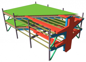 This figure provides a cutaway view, showing how the subsystems are integrated: The floor plenum, with access floor supported on pedestals; A supply air system (shown in red), consisting of: a vertical supply shaft from the air-handling units at the bottom of the building, horizontal manifold ducts, and supply ducts delivering air to the various parts of the floor plenum. Delivering air to remote parts of the floor plenum through insulated ducts assures that the thermally conditioned air gets everywhere without degrading the quality of the thermal conditioning; A cutaway view of the concrete floor deck on top of the secondary beams; A cutaway view of thermal insulation on top of the concrete floor deck. This provides thermal separation between the supply plenum in the floor above and the return plenum in the ceiling below; A cutaway view of the ceiling, which is mounted just below the secondary beams; The steel secondary beams mounted on the top of the steel primary beams; A return-air system (shown in blue), consisting of the ceiling plenum (between the secondary beams), horizontal manifold ducts, and a vertical chase which transports return air back to the air-handling units at the bottom of the building; To facilitate both the free flow of return air above the ceiling and keeping the ceiling high, the primary beams have been placed below the secondary beams. This arrangement allows the air to pass up through the ceiling and then return between the secondary beams above the ceiling.
The building has been occupied for a few years and is the topic of several ongoing post occupancy evaluations. The building has established a reputation as a model of energy efficiency and effective systems integration and has been visited by hundreds of architects, engineers, government officials, and corporate entities who are in the process of commissioning the design of new office buildings.
2. An integrated roofing system incorporating dynamically adjustable, remote shading for daylighting apertures
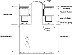 The existing paradigm for commercial buildings is an opaque flat roof consisting of waterproofing membrane, rigid insulation, and corrugated steel decking supported by steel joists. In this scheme, there is an interstitial volume that houses the various building systems, including: waterproofing, insulation, structure, HVAC, electrical power, communications, plumbing, and fire protection. Often, to make the design process simpler, each system is given its own layer. This uncoordinated layering of systems also makes it extremely challenging to introduce natural light to the building. To get natural light through such a roof, architects often “tunnel” vertically through the interstitial volume, trying to find the small vertical shafts that manage to sidestep all the random systems elements. The resulting “light well” constricts the flow of light and causes major light losses due to the number of bounces that are involved before the light can find its way down through the tunnel and into the occupied space (Figure 1, above). It also selects against light that moves laterally, which means that light entering the occupied space tends to be heading predominantly downward, limiting the coverage of the light. This configuration requires curbing and complex detailing to make it waterproof. These curbs add to the area of the thermal envelope, increasing the unwanted thermal gains and losses. These curbs are structural, involving dense materials that become thermal bridges that undermine the effectiveness of the thermal envelope. The curbs also add to the depth of the light well, further reducing the optical efficiency of the system.
These apertures are typically capped off using glazing that produces an aperture that is effectively horizontal from the point of view of the acceptance of solar radiation. Horizontal apertures have two major advantages: They face the full sky vault, including the part of the sky that tends to be brightest under marginal, overcast conditions, which allows them to gather the maximum amount of diffuse light from the sky; There are many situations where the only available natural light is from overhead. (This will commonly occur in urban environments, with tall surrounding structures, or building sites surrounded by tall trees). However, horizontal apertures have the huge disadvantage that they face upward towards the fierce overhead summer sun. Beam sunlight has about ten times as much heat content as diffuse light from the sky. If the horizontal apertures are sized large enough to admit adequate light from the sky when a cloud is blocking the beam sunlight, when the cloud moves away, there will be an extreme thermal overload. Alternately, if the horizontal apertures are sized small enough to avoid thermal overload when the beam sunlight is on the apertures, then they will harvest only about one tenth of the desired amount of light when a cloud blocks the beam sunlight.
The flat roof paradigm described above has been almost a century in its evolution and is deeply engrained in the standard building design and construction process. It needs to be serious rethought and challenged.
An integrated roofing system incorporating dynamically adjustable, remote shading elements, structure, HVAC and electric lighting is currently under investigation by the research team.The key components of the system are:
- A Protective Glazing that protects all the other elements of the roof system from wind, rain, snow, ice, and dirt.
- A light-weight, Insulated Ceiling that is the primary thermal barrier for the roof.
- Small Daylight Apertures in the insulated ceiling, sized to admit appropriate amounts of daylighting to adequately illuminate the occupied space without creating any thermal overload.
- Insulated Glazing in the daylighting apertures, to complete the thermal barrier.
- Remote Shading Elements that track the sun to block the beam sunlight from entering the daylighting apertures. This protects the building occupants from glare and prevents the extreme thermal overload that can result from allowing summer sun to enter the building.
- An extremely reflective top surface on the insulated ceiling, to reflect away unwanted solar radiation. This surface can be a very light-weight mirror, since it will be protected from exposure to the elements.
This system has several attractive features:
- It works equally well at all orientations of the building relative to the solar cardinal directions, which drastically broadens its appeal to designers who want to decide the building orientation based on local conditions, such as sight lines or alignment with the street front.
- It is efficient in harvesting daylight, since the daylight apertures face the entire sky. The apertures in the thermal envelope should be sized to admit ample quantities of light for illumination while avoiding significant thermal overload, which requires an area in the range of 10% to 15% of the roof area.
- It is 100% effective in protecting the daylight apertures from unwanted solar heat gains.
- Locating the shading elements remotely from the apertures allows them to block the beam sunlight while blocking very little of the diffuse skylight, which is the target daylight source. This keeps the optical efficiency of the system high. The shading elements should be just big enough to fully shade the apertures, but no larger.
- The tracking mechanisms that move the shading elements can move very slowly over the course of the day, making them more robust and less noisy than any existing dynamic shading elements.
- The roof is more effective than other roofs in reflecting away unwanted solar heat, since the mirrored top surface can be extremely reflective and will remain so, by virtue of being protected from the elements by the protective glazing.
- The insulating barrier is very efficient, since it has minimal surface area and is not violated by structural elements such as curbs, which are significant thermal bridges in the construction of conventional skylights. Keeping this insulating barrier non-structural is crucial to achieving the highest possible thermal integrity.
Such a system was not possible even a few years ago, since no appropriate lightweight, structural, ultra-violet-resistive material existed to serve as the protective glazing. This is an illustration of the importance of using systems to identify desirable material properties. Continuing the evolution of this type of building system hinges on being able to conceptualize and assess system needs and to identify future material properties that will provide the best possible system performance.
3. A multi-tier dynamic light shelf system integrated with curtain wall facade, photovoltaics and LED lighting in commercial buildings
To use natural light in buildings, architects’ designs often offer plenty of glass for light, but that light, if not successfully controlled, brings with it too much heat, forcing engineers to increase the cooling tonnage. Too much uncontrolled light also forces occupants to lower blinds to cut down on glare. Occupants are very likely to lower the blinds when direct sunlight reaches their work area, but seldom raise them for useful daylight admittance even after the unwanted conditions fade away. This means that blinds tend to remain closed for long periods of time. The sheer amount of blinds and other window coverings on modern buildings are a testament to unachieved goals of daylighting and energy efficiency in buildings. The lowered blinds will:
- Reduce the availability of daylight and thus increase the use of electric lights: Electric lighting with control systems such as photo-controlled sensors and continuous dimming based on daylight availability has the potential to significantly reduce the electrical energy consumption buildings. However, these systems do not provide the anticipated energy savings when installed in real buildings, because the lowered blinds reduce the amount of daylight incident on the photo sensor for electric lighting control.
- Cut off the view to the outside: Although a certain degree of enclosure by opaque walls creates a sense of protection, most would agree that view matters. There is a direct relationship between higher satisfactions associated with a view to outside and increased work productivity.
Numerous systems/products have been developed with the attempt to maximize the benefit of daylight, such as spectrally selective glazing, solar filtering materials (e.g. fritted glass), exterior overhang, exterior louvers, etc. Very few products, however, were successful in delivering both useful daylight and satisfactory view to the users.
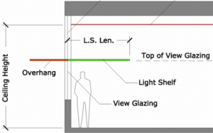 A light shelf is a small area of horizontal reflecting surface mounted just below the daylight glazing and above eyelevel. There are three functions to a light shelf system: 1. Reflect light deeper into the building, thereby providing more light in the interior; 2. Block excessive light from entering spaces close to the perimeter wall; 3. Maintain the view through the daylight glazing, which is especially desirable for users sitting away from windows. Depending on the overall ceiling height of the space, the light shelf usually needs to be fairly deep to fully intercept the sunbeam admitted through daylight glazing in all seasons. For example, in Raleigh, North Carolina (latitude 36 degrees), the depth of the light shelf mounted at 7 feet above the floor should be about 6 feet for a 10 feet high ceiling.
Although this design achieves the three functions of a light shelf listed above, the following challenges have limited its application in practice:
– A 6-foot deep light shelf may be visually intrusive to some users, especially to the ones who work directly below the shelf, as it can feel overwhelming due to its dimension and mounting height.
– It is required by codes that, for any horizontal surfaces deeper than 4 feet, sprinkler heads be installed above and below that surface for fire protection purposes. This requirement not only significantly adds to the cost and complexity of the system, but also makes it less aesthetically desirable by having to expose the sprinkler pipes visually.
To solve these problems associated with the deep (6 feet) light shelf, a narrower version (4 feet) is explored as the first step in this project. The reduced dimension is visually less intrusive and overwhelming and, more importantly, eliminates the need for sprinklers. The device, which is fixed in dimension and mounting height, is effective for intercepting direct sunbeams for the majority of the months in Raleigh, NC. However, it fails when solar angles are low during the winter months.
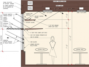 A Multi-Tier Dynamic Light Shelf (MTDLS) is proposed in this project to address the above issues. The MTDLS system features a 4-ft deep fixed light shelf and a dynamically controlled upper light shelf. During winter months when solar angles are lower, the upper light shelf will be set in place to help intercept the sunbeams, whereas for the rest of the year when solar angles are higher, it will be “removed” by lowering to the top of the fixed shelf so that the daylight and the view through the daylight glazing can both be maximized.
